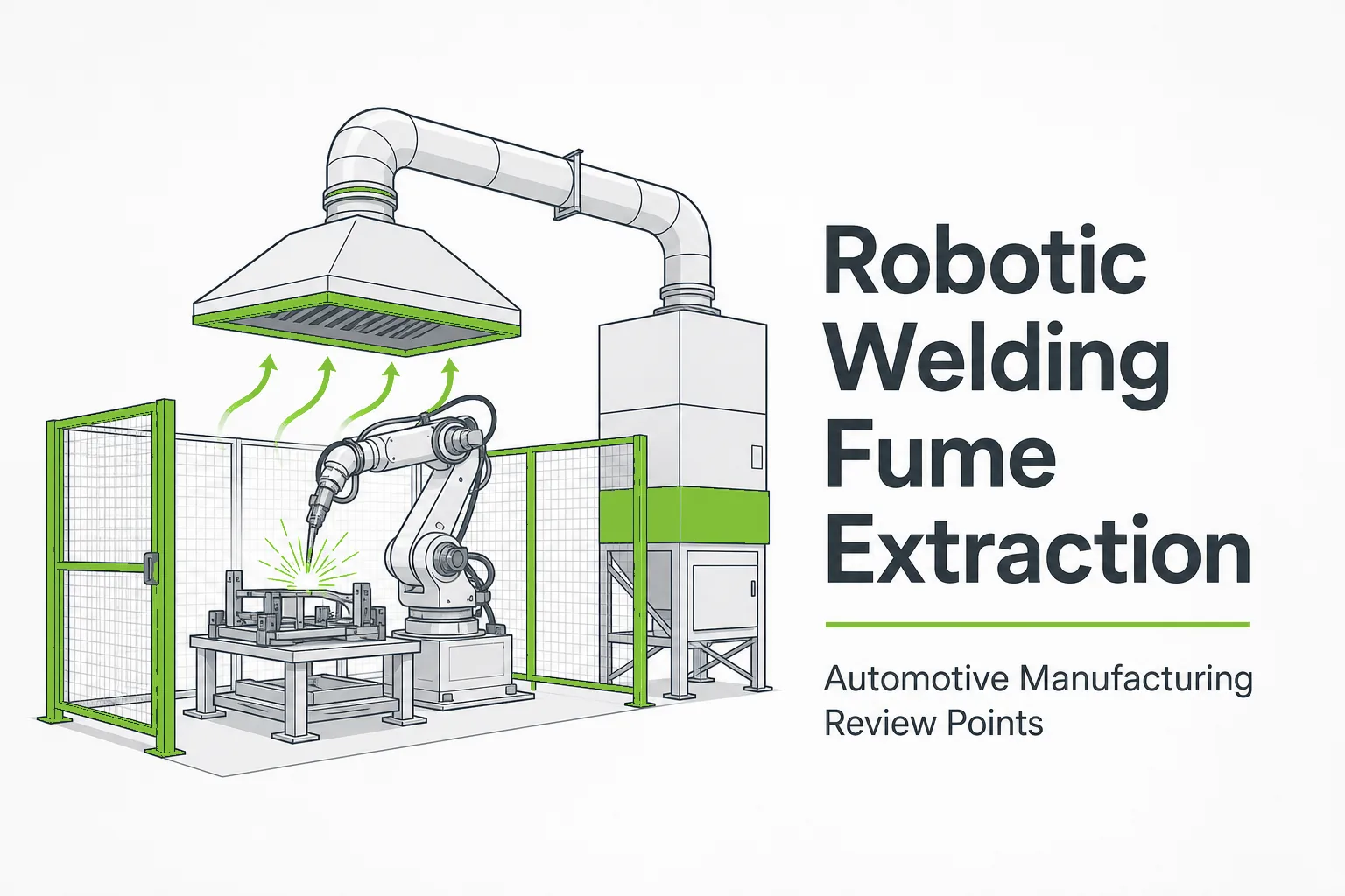
Robotic welding cells are now standard in automotive body shops, parts plants and many other metalworking facilities. They weld faster and longer than manual stations, which also means they generate welding fume at a higher and more continuous rate. Because the robot works at a fixed position, the fume source is predictable, and that makes source capture the natural starting point for any extraction review.
This article explains how robotic welding fume extraction works, which capture and hood options fit different robot cells, how the captured air connects to a central dust collection route, and what project data AIER needs to review a system. It is written for plant engineers, EHS managers and project buyers in the automotive manufacturing industry and other plants running robot welding lines. It does not replace workplace exposure assessment, local regulations or site-specific engineering design.
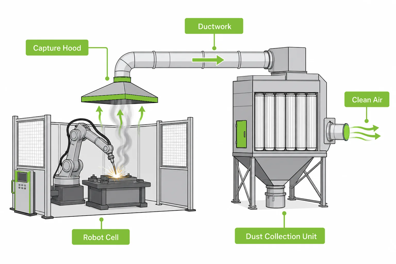
Robotic welding fume extraction captures fume at the cell and moves it through ductwork to a filtration unit before the cleaned air is discharged or returned.
What Is Robotic Welding Fume Extraction?
Robotic welding fume extraction is the capture and filtration of welding fume generated by robot welding cells, usually through a ventilation hood or enclosure positioned over or around the cell and connected to a dust collection system that filters the fume-laden air.
The principle is source capture: collect the fume where it is generated, before it rises into the building air and spreads across the workshop. A robot cell suits this approach better than most manual stations because the arc position, part orientation and cycle timing are fixed and repeatable. Once the capture point is designed around the cell, it keeps working shift after shift without depending on operator behavior.
A complete system has three parts that must be reviewed together: the capture device (hood, enclosure or torch-mounted extraction), the ductwork that moves the air, and the filtration unit that removes the fume particles. Buying any one part without reviewing the other two is the most common reason these projects underperform.
Why Robotic Welding Fume Is Different from Manual Welding
Welding fume itself is similar — fine metal particles formed when the wire and base material vaporize and condense. According to OSHA, welding fume can contain metals such as manganese and chromium compounds depending on the wire and base material, which is why workplaces control fume exposure around welding operations. What changes with robots is the operating pattern.
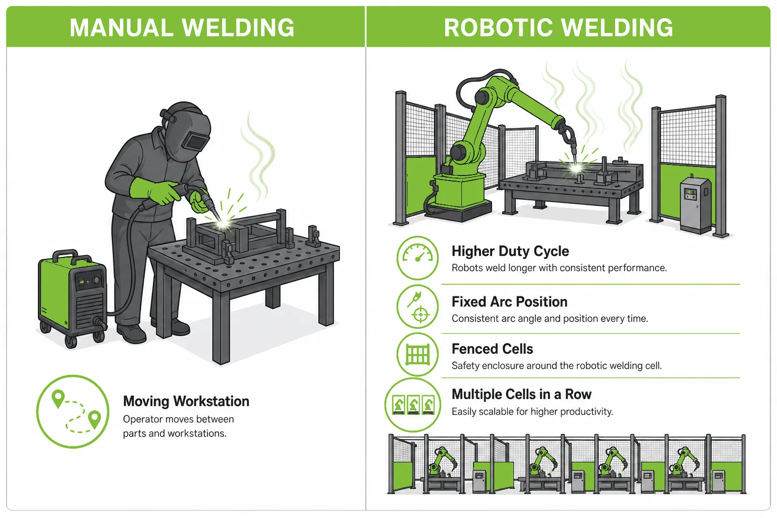
Robot cells weld with a much higher arc-on time at a fixed position, so the fume load is higher but easier to capture at the source.
- Higher duty cycle: a robot can hold a much higher arc-on time than a manual welder, so the fume generated per hour is significantly higher at the same process settings.
- Fixed, repeatable source: the arc always burns inside a known envelope, which makes hoods and enclosures far more effective than they are over a moving manual workstation.
- Cells are already fenced: most robot cells have safety fencing or enclosures for machine safety, which can often be extended into a fume enclosure with extraction.
- Multiple cells in a row: automotive lines usually run several cells side by side, which favors one central dust collection system over many standalone units.
- No operator inside the cell: capture design can prioritize containment instead of keeping a breathing zone clear, although the surrounding workshop still needs protection.
These differences are why a robotic welding line deserves its own extraction review instead of copying whatever the manual welding bays use.
Capture Options for Robot Welding Cells
There are four common ways to capture fume from a robot welding cell, from robotic welding ventilation hoods above the cell to torch-mounted extraction at the arc. They differ in containment, space demand and how much airflow the filtration system must handle, so the choice drives the size of everything downstream.
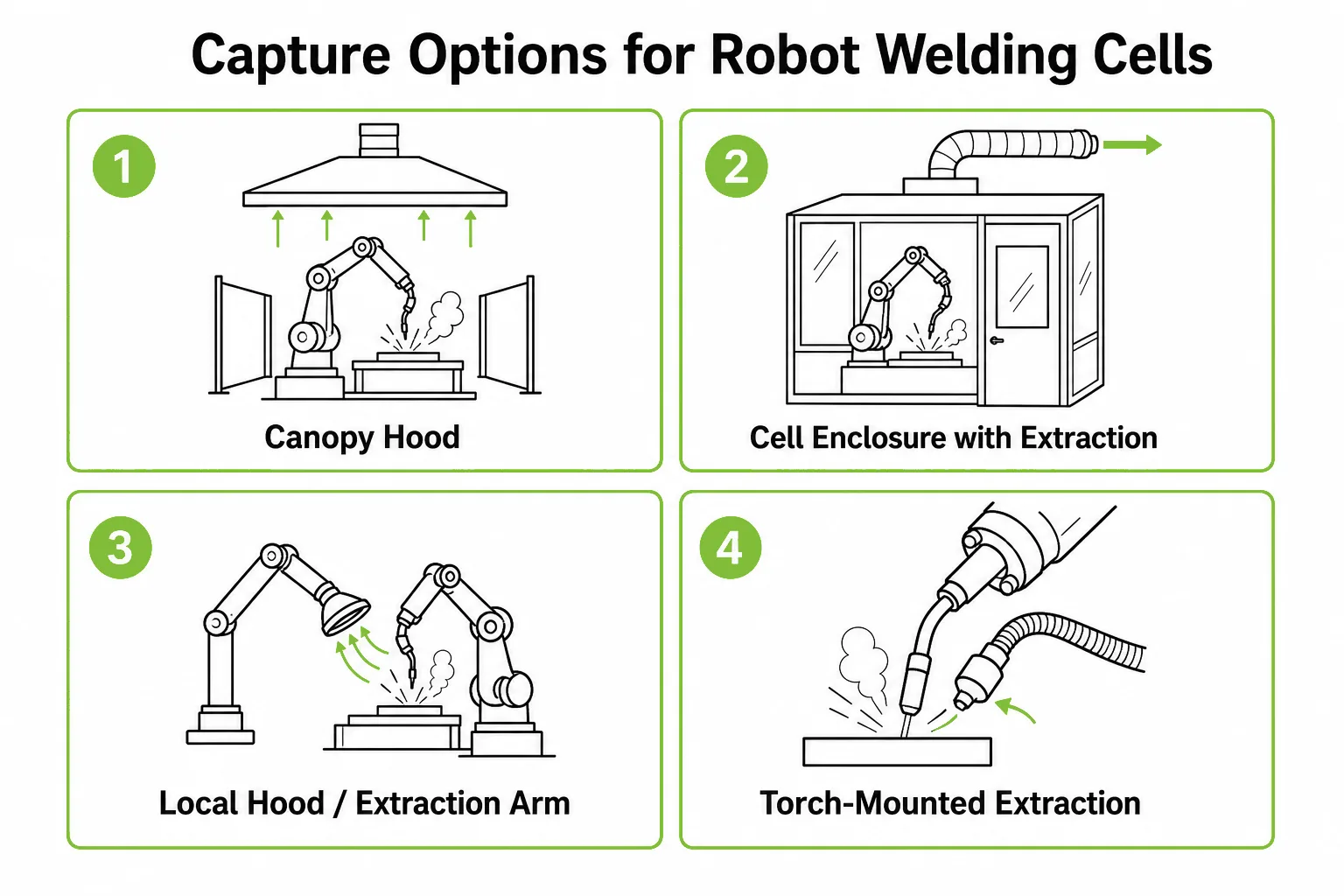
Capture options for robot welding cells range from canopy hoods above the cell to full enclosures and torch-mounted extraction.
| Capture Option | Where It Fits | Review Points |
|---|---|---|
| Canopy hood above the cell | Cells with crane or part access from the side, hot rising fume, common retrofit choice | Hood coverage versus cell footprint, cross-draft interference, height above the arc |
| Cell enclosure with extraction (welding ventilation hood over an enclosed cell) | New lines or cells that already have safety fencing; best containment | Door and opening positions, part loading path, keeping the enclosure under slight negative pressure |
| Extraction arm or local hood near the fixture | Small cells or single-fixture stations where a full hood is not practical | Arm position versus robot motion envelope, repositioning discipline, capture distance |
| Torch-mounted extraction (fume extraction gun style) | Capture at the arc itself; used on some robot torches and common in manual MIG | Torch weight and dress pack compatibility, capture share, still usually combined with a hood |
In practice, many automotive cells end up with a welding fume extraction hood — sometimes called a welding exhaust hood — or an enclosure as the primary capture device, sometimes combined with torch extraction on high-fume processes. The right answer depends on the cell layout and how parts move in and out, which is exactly what the review stage should examine.
Hood and Enclosure Review Points
Robotic welding ventilation hoods look simple, but most capture problems come from details that were not reviewed against the actual cell. The same review points apply to automated welding cell hoods on new lines and retrofit projects alike. These are the points AIER checks before sizing anything.
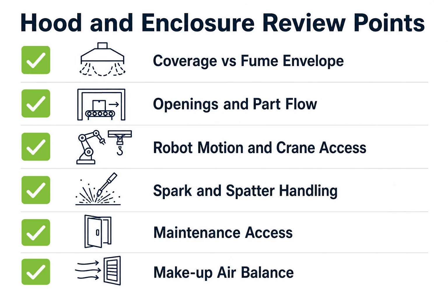
Hood and enclosure review should cover coverage area, opening positions, part loading, maintenance access and spark handling.
- Coverage versus the fume envelope: the hood must cover where the fume actually rises, including secondary arcs and tack stations, not only the main fixture.
- Openings and part flow: conveyor slots, turntable gaps and door openings all leak; their size and position decide whether the enclosure holds containment.
- Robot motion and crane access: the hood must clear the robot envelope, cable dress and any overhead crane path used for fixture changes.
- Spark and spatter handling: welding generates sparks; the extraction path should include spark pre-separation or arresting before the filter media, and the duct route should avoid horizontal dust settling.
- Maintenance access: filters, ducts and the hood interior need cleaning access without dismantling the cell.
- Make-up air and workshop airflow: extracted air leaves the building or returns filtered; either way the workshop airflow balance should be checked so neighboring stations are not affected.
None of these points require design parameters at the inquiry stage. They require drawings, photos and an honest description of how the cell runs, which is cheaper to review before the hood is built than after.
From Capture to Filtration: The Central Dust Collection Route
Captured air still has to go somewhere. For a single small cell, a standalone filter unit next to the cell can work. For automotive lines with several cells, the usual route is a central system: hoods from each cell connect into common ductwork that leads to one dust collector sized for the combined airflow.
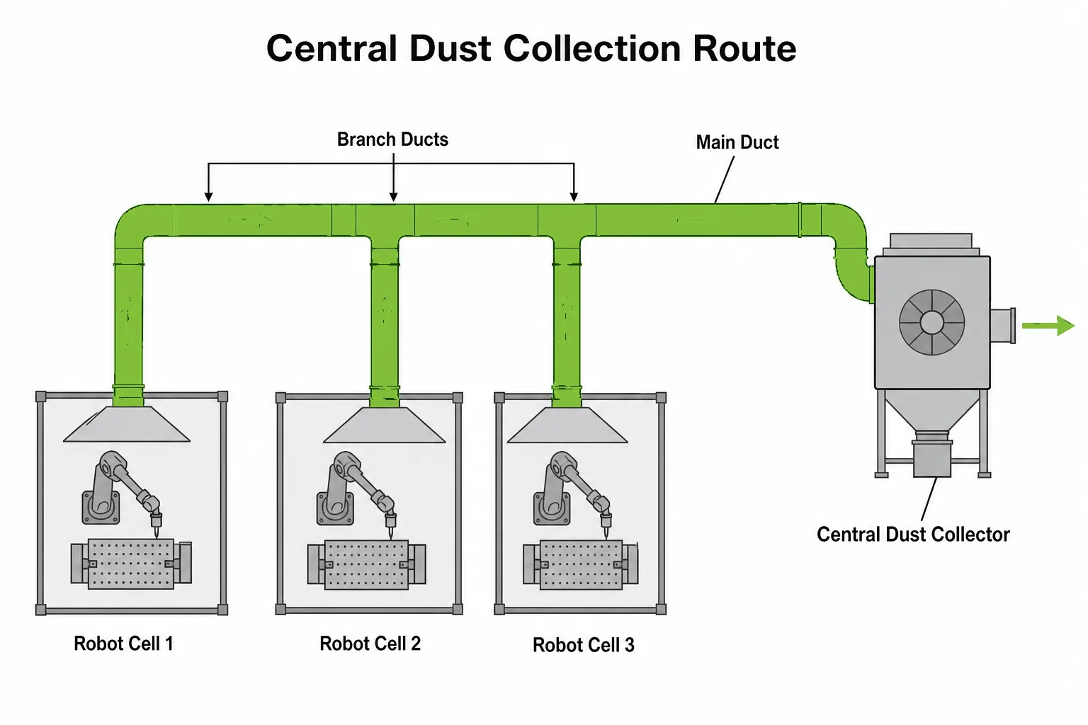
Multiple robot welding cells usually connect through branch ducts to one central dust collection system instead of separate standalone units.
A central route reduces the number of filter units to maintain and keeps the plant floor clear, but it makes duct design and airflow balancing more important: every branch must pull its share, including the cell furthest from the collector. The review logic is the same one described in our dust collection system design article — capture points first, then airflow, then duct routing, then the collector — applied to welding fume instead of process dust.
The choice between standalone and central is a project decision, not a catalog decision. Cell count, spacing, future line expansion and available floor or roof space usually decide it, and industrial dust collection systems can be configured either way.
Filter Equipment for Welding Fume
Welding fume particles are fine, dry and mostly metallic, which points the filtration review toward pulse jet cleaned filter equipment. Coarser dust from grinding and finishing is a separate duty with its own review, covered in our metal dust collection system article. Two AIER product families are most relevant for robot welding duty.
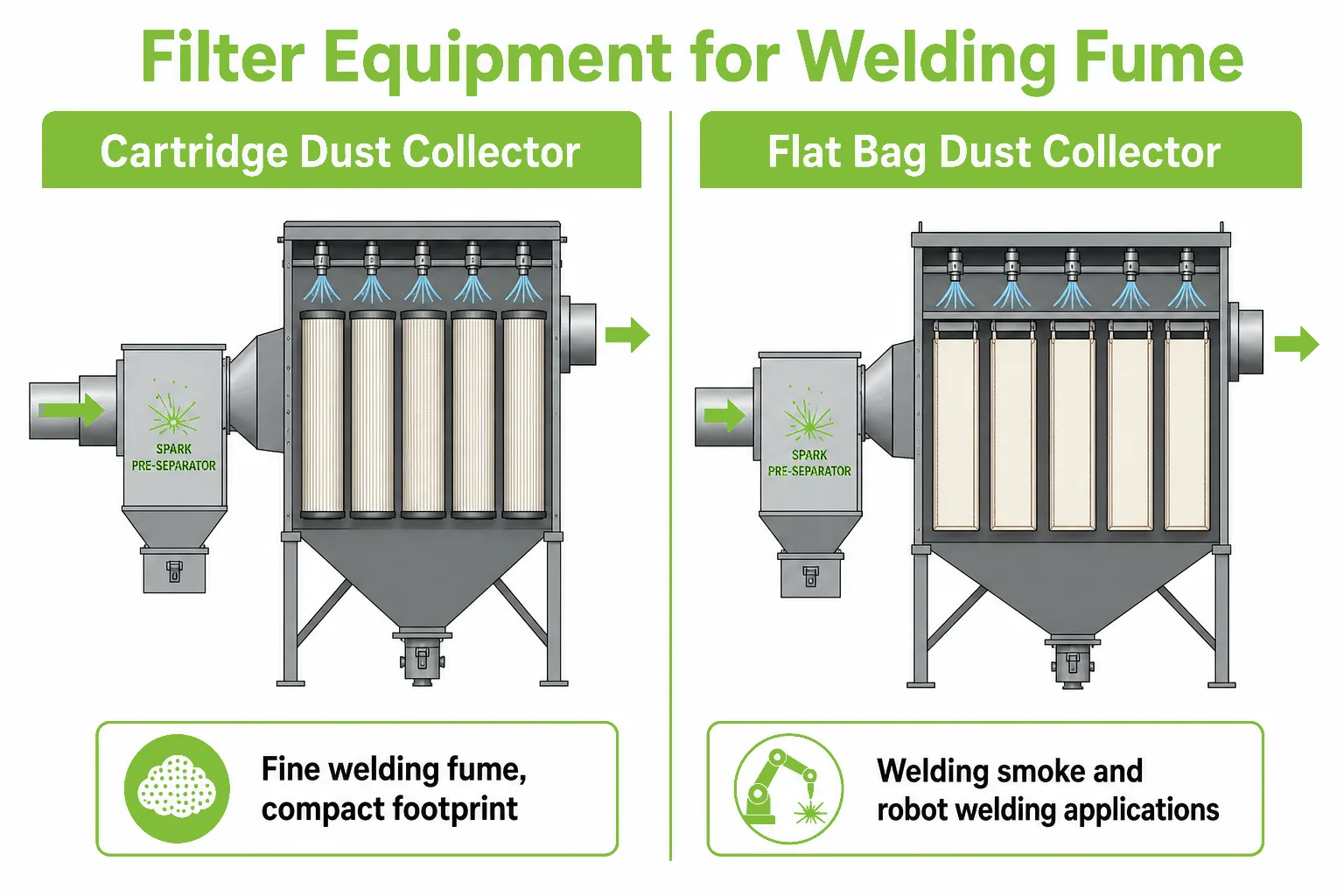
Cartridge and flat bag dust collectors with pulse jet cleaning are the common filter routes for robot welding fume, selected by fume load and layout.
| Filter Route | Where It Fits | Review Points |
|---|---|---|
| Cartridge dust collectors | Fine welding fume, compact footprint next to lines, common welding-fume choice | Filter media selection, pulse cleaning settings, spark pre-separation upstream |
| Flat bag dust collector | Welding smoke and robot welding applications listed in the AIER catalog; flat bags with pulse jet cleaning | Bag material, cleaning cycle, hopper discharge arrangement |
Whichever filter route fits, the same operating rules apply as for any pulse jet collector: watch the pressure drop trend, keep the compressed air supply healthy and replace media based on condition. Our dust collector maintenance article covers that review logic in detail.
Common Mistakes in Robotic Welding Fume Extraction Projects
Most underperforming systems AIER reviews share the same selection-stage gaps. These are the patterns to avoid.
- Buying a hood without a system review: a hood with no matched airflow, duct route and filter unit is just a metal roof over the cell.
- Copying the manual welding bay setup: robot cells run a much higher duty cycle; an extraction point sized for occasional manual welding will fall behind.
- Ignoring openings: conveyor slots and door gaps that were never reviewed are the usual reason an enclosure fails to contain fume.
- No spark pre-separation: sparks reaching the filter media create damage and housekeeping problems that look like filter quality issues but are actually layout issues.
- Undersizing for the farthest cell: in central systems, the last branch on the run gets weak extraction when duct balancing was skipped.
- Forgetting maintenance from day one: filters and ducts on a welding line load up as a consumable process; access and a replacement plan belong in the project scope.
- Treating extraction as the whole answer: capture reduces fume spread, but workplace exposure assessment and process settings remain the plant’s responsibility under local regulations.
Information AIER Needs for a Robotic Welding Fume Review
A robotic welding fume extraction review moves fastest when the inquiry includes the welding process and cell layout instead of only a target airflow. This is the information AIER uses to judge the capture method, duct route and filter selection.
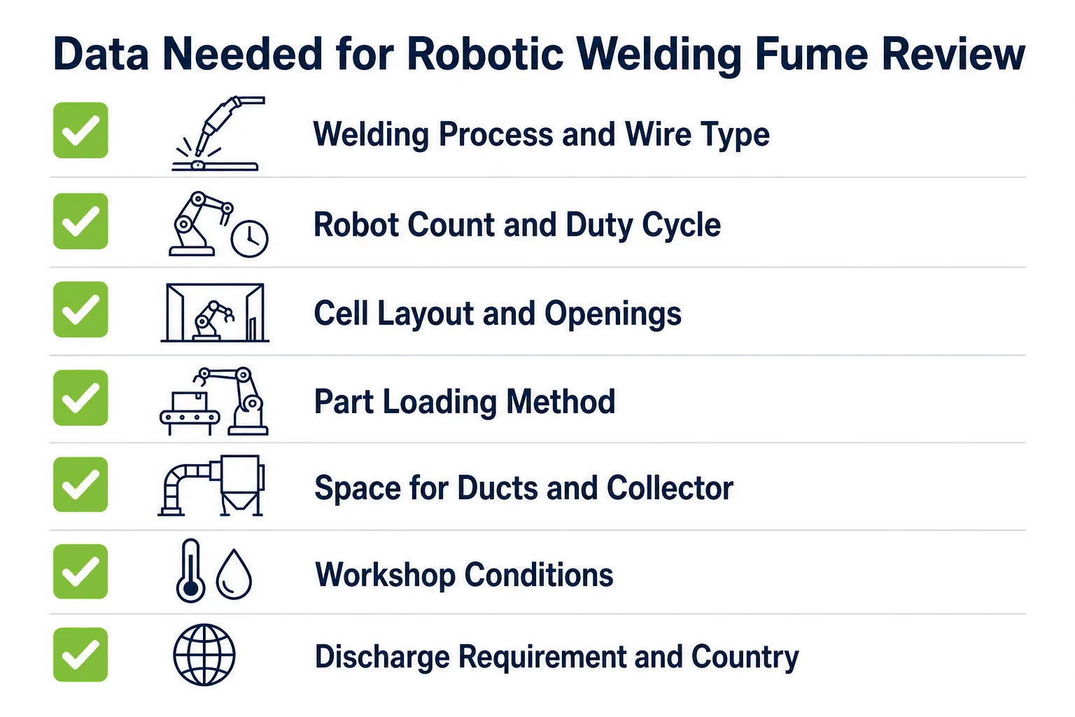
AIER reviews the welding process, robot count, duty cycle, cell layout and workshop conditions before recommending a capture and filtration route.
| Data to Prepare | Why It Matters |
|---|---|
| Welding process, wire type and base material | Decides the fume character and the filter media review |
| Number of robots, cells and duty cycle | Decides the fume load and whether a central or standalone route fits |
| Cell layout drawings or photos, including fencing and openings | Decides the capture option and hood or enclosure geometry |
| Part loading method (conveyor, turntable, crane, manual) | Shows where openings must stay clear and where leakage risk sits |
| Available space for ducts and the collector (floor or roof) | Affects duct routing and equipment placement |
| Workshop conditions and existing ventilation | Affects make-up air, cross-drafts and airflow balance |
| Discharge or return-air requirement and installation country | Defines the emission path and project requirements |
If your plant is adding robot welding cells or fixing an underperforming extraction setup, contact AIER with your welding process, cell count, layout drawings and duty cycle. AIER will review whether a canopy hood, cell enclosure, torch extraction or a combined design fits your line, and how the capture points should connect to the filtration system.
FAQ
What is robotic welding fume extraction?
Robotic welding fume extraction is the capture and filtration of welding fume from robot welding cells, usually through a hood or enclosure over the cell connected by ductwork to a dust collection system. It works as source capture: the fume is collected where the arc generates it, before it spreads into the workshop.
Which capture hood fits a robotic welding cell?
Cells with side access for cranes or conveyors often use a canopy hood above the cell, while cells that already have safety fencing suit a full enclosure with extraction, which gives the best containment. Small single-fixture stations may use a local hood or extraction arm. The cell layout and part loading path decide the choice, not the hood catalog.
Can one dust collector serve multiple robot welding cells?
Yes. Automotive lines usually connect several cells through branch ducts to one central dust collection system. The duct design must be balanced so every branch pulls its share, including the cell farthest from the collector, which is why the duct route is reviewed together with the collector size.
What filter type handles welding fume?
Welding fume is fine and dry, so pulse jet cleaned filter equipment is the common route. Cartridge dust collectors are a frequent choice for welding fume, and the AIER flat bag dust collector catalog also lists welding smoke and robot welding among its applications. The final selection depends on fume load, layout and maintenance preference.
Does welding fume extraction need spark pre-separation?
Welding generates sparks and spatter, so the extraction path should include spark pre-separation or arresting before the filter media. Skipping it leads to filter damage and housekeeping problems that are often misread as filter quality issues.
What information is needed for a robotic welding fume extraction quote?
Provide the welding process and wire type, base material, number of robots and duty cycle, cell layout drawings or photos including fencing and openings, part loading method, available space for ducts and the collector, workshop conditions and the installation country. AIER reviews the capture method, duct route and filter selection based on the actual line.