
Dust collection system design is not just choosing a dust collector from a catalog. In an industrial plant, the system has to capture dust at the source, carry it through ductwork at the right velocity, separate dust from the air stream, discharge collected material safely and keep maintenance access practical. If the first sizing step is wrong, even a good collector can perform poorly.
This article explains how industrial dust collection system design and sizing should be reviewed before equipment is selected. It is written for factories, production lines and project buyers, not for woodshop or DIY dust collection. The goal is to help you prepare the data AIER needs to review an industrial dust collection project.
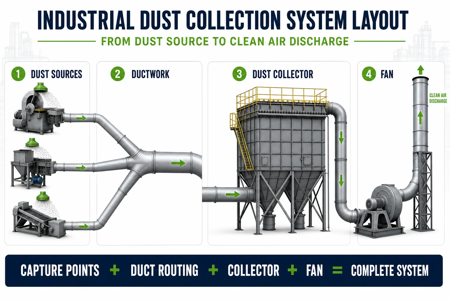
An industrial dust collection system links dust sources, capture points, ductwork, collector equipment, a fan and discharge points into one airflow path.
What Does Dust Collection System Design Include?
A complete dust collection system design normally includes four connected tasks:
- Capture: identify where dust is generated and decide whether it should be captured by a hood, an enclosure, a source capture device or an ambient system.
- Convey: move the dust-laden air through ductwork fast enough to prevent settling, while keeping duct resistance reasonable.
- Collect: select the collector type, filter area, cleaning method, hopper discharge and fan according to the dust and airflow.
- Maintain: leave space for filter replacement, hopper access, differential pressure checks and safe shutdown procedures.
These tasks cannot be separated. A hood that captures too little air makes the collector look undersized. Ductwork with too many bends makes the fan work harder. A collector with too little filter area runs at high pressure drop. A system with poor maintenance access may be neglected even if the original calculation was correct.
Start With Dust Sources and Capture Points
The first design step is to map each dust source in the plant. Common industrial dust sources include transfer points, crushers, mixers, bag dumping stations, dryers, grinders, welding stations, powder filling machines and material handling equipment. Each source needs a capture method that fits the process layout.
| Capture Method | Best Fit | Design Concern |
|---|---|---|
| Local hood | Open dust generation points such as dumping, grinding or transfer | Hood distance, side drafts and worker access affect capture efficiency |
| Partial enclosure | Conveyors, screening points, filling points and dusty process openings | Enclosure leakage and make-up air path must be controlled |
| Source capture arm | Welding, polishing or intermittent workstations | Requires operator positioning and enough capture velocity at the source |
| Ambient air filtration | Large areas where source capture is not practical | Does not replace source capture for high dust loads or hazardous dust |
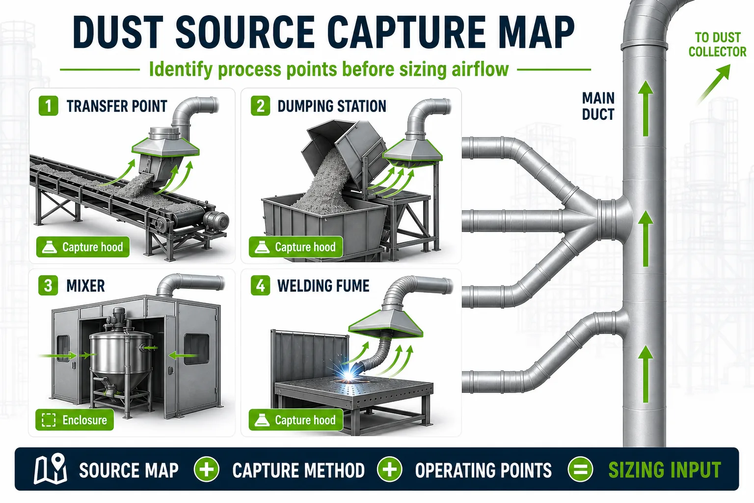
Dust source mapping should identify where dust is generated, how it escapes and which capture method can control it without disturbing production.
The most common early mistake is sizing the collector before the capture points are defined. Collector size depends on airflow, and airflow depends on the hood opening area, capture velocity, process enclosure leakage and how many points operate at the same time.
Airflow and CFM Sizing for Industrial Dust Collection
Dust collector sizing starts with airflow. In English-unit calculations, airflow is often expressed as CFM. In metric projects, it is usually expressed as m3/h. The basic relationship is simple:
Airflow = capture velocity x open area
This relationship is useful, but it is not enough by itself. Industrial dust collection system design also needs to consider simultaneous operation, process enclosure leakage, duct losses, collector pressure drop and future expansion. A dust collector CFM chart or dust collector calculator can help with early estimates, but it cannot replace project data.
| Sizing Question | Why It Matters | Data to Prepare |
|---|---|---|
| How many dust points run at the same time? | Defines peak airflow instead of adding every unused pickup | Operating schedule and process sequence |
| How large are the hood or enclosure openings? | Open area drives required airflow | Hood dimensions, enclosure openings, leakage paths |
| What capture velocity is needed? | Too low fails to capture dust; too high wastes fan energy | Dust release energy, source distance, cross drafts |
| Will air be exhausted or returned indoors? | Affects fan, filtration, make-up air and safety review | Plant ventilation strategy and local requirements |
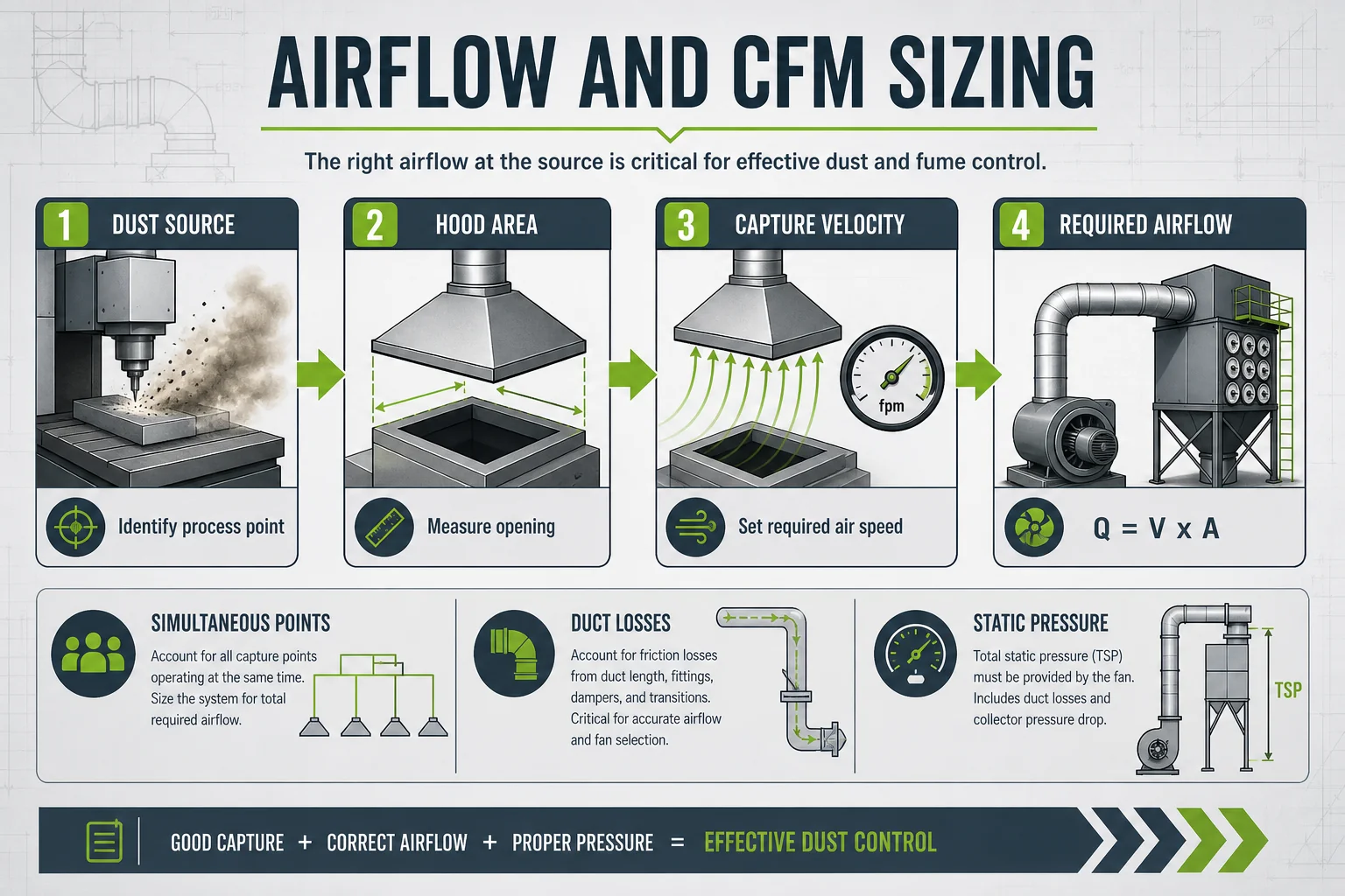
Airflow sizing starts with capture points and simultaneous operation, then checks whether the fan and collector can handle the required volume at the design pressure.
For AIER projects, airflow is reviewed together with dust concentration, temperature and collector type. A high airflow with low dust loading may favor a different design from a lower airflow with heavy abrasive dust.
Ductwork, Conveying Velocity and Static Pressure
After dust is captured, ductwork must keep it moving. If the conveying velocity is too low, dust can settle in horizontal ducts or build up at elbows. If velocity is too high, the system may waste energy, increase abrasion and create unnecessary noise.
Dust collection ductwork affects three things:
- Conveying velocity: the air speed needed to keep dust suspended in the duct.
- Static pressure: the resistance the fan must overcome through hoods, ducts, elbows, collector filters, outlet duct and stack.
- System balance: the way branches share airflow when multiple pickup points connect to one main duct.
Long duct runs, sharp elbows, undersized branches, leaking dampers and poor transitions can increase pressure loss. A fan selected only by airflow, without static pressure review, may fail to deliver the required capture performance after the full system is installed.
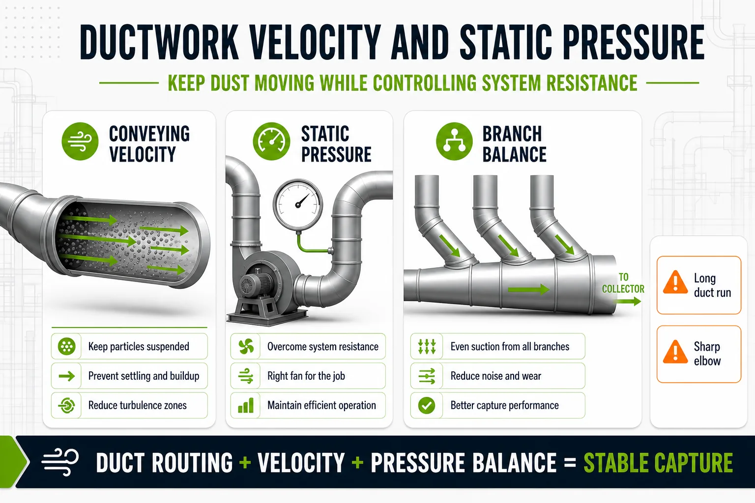
Ductwork design should reduce unnecessary resistance while keeping conveying velocity high enough to prevent dust settling.
For combustible or sticky dust, duct design also needs cleanout access and a safety review. Do not assume that a straight calculation alone solves these risks. Regulatory agencies such as OSHA discuss combustible dust hazards as a workplace safety concern, and project-specific evaluation may be required.
How Dust Properties Affect Collector Selection
Once airflow and duct conditions are understood, the collector type can be selected. Dust properties often decide whether a cartridge collector, baghouse collector, flat bag collector, round bag collector or sintered plate collector is more suitable.
| Dust or Gas Condition | Why It Matters | Design Impact |
|---|---|---|
| Fine dry dust | Can pass deep into filter media if the element is not suitable | Review cartridge filters, membrane bags or sintered plates |
| High dust loading | Increases filter cleaning demand and hopper discharge load | Review baghouse, inlet distribution and dust discharge |
| Abrasive dust | Can wear ducts, inlets, cages and filter elements | Review inlet design, velocity and wear protection |
| Moist or sticky dust | Can blind filters and bridge in hoppers | Review temperature control, filter surface and hopper design |
| Hot gas | Limits filter material and affects fan and duct selection | Review high-temperature bags or other treatment routes |
| Combustible dust | May require explosion protection and safe discharge design | Needs project-specific safety review |
Dust loading also affects the air-to-cloth ratio, which compares airflow with available filter area. A collector with too little filter area may have high pressure drop, frequent cleaning cycles and short filter life. A collector with excessive filter area may cost more than needed and take unnecessary floor space.
Choosing Between Cartridge, Baghouse and Sintered Plate Collectors
AIER supplies several dry dust collection equipment directions, and each fits a different project condition. The design should compare the dust, airflow, temperature, footprint and maintenance expectations before selecting the collector body.
| Collector Type | Typical Fit | Design Note |
|---|---|---|
| Cartridge dust collector | Fine dry dust, welding fume, laser fume, compact layouts | Best when dust is dry and not too heavy or sticky |
| Baghouse dust collector | High dust loading, high air volume, more demanding process dust | Filter bag material and cleaning system must match the dust |
| Flat bag dust collector | Height-limited installations and compact process areas | Useful when vertical space is restricted |
| Round bag dust collector | Round housing layouts and bag filtration needs | Can fit certain plant layouts and dust discharge needs |
| Sintered plate dust collector | Fine, sticky or high-value dust where long element life matters | Higher initial investment may be justified by element life and stable performance |
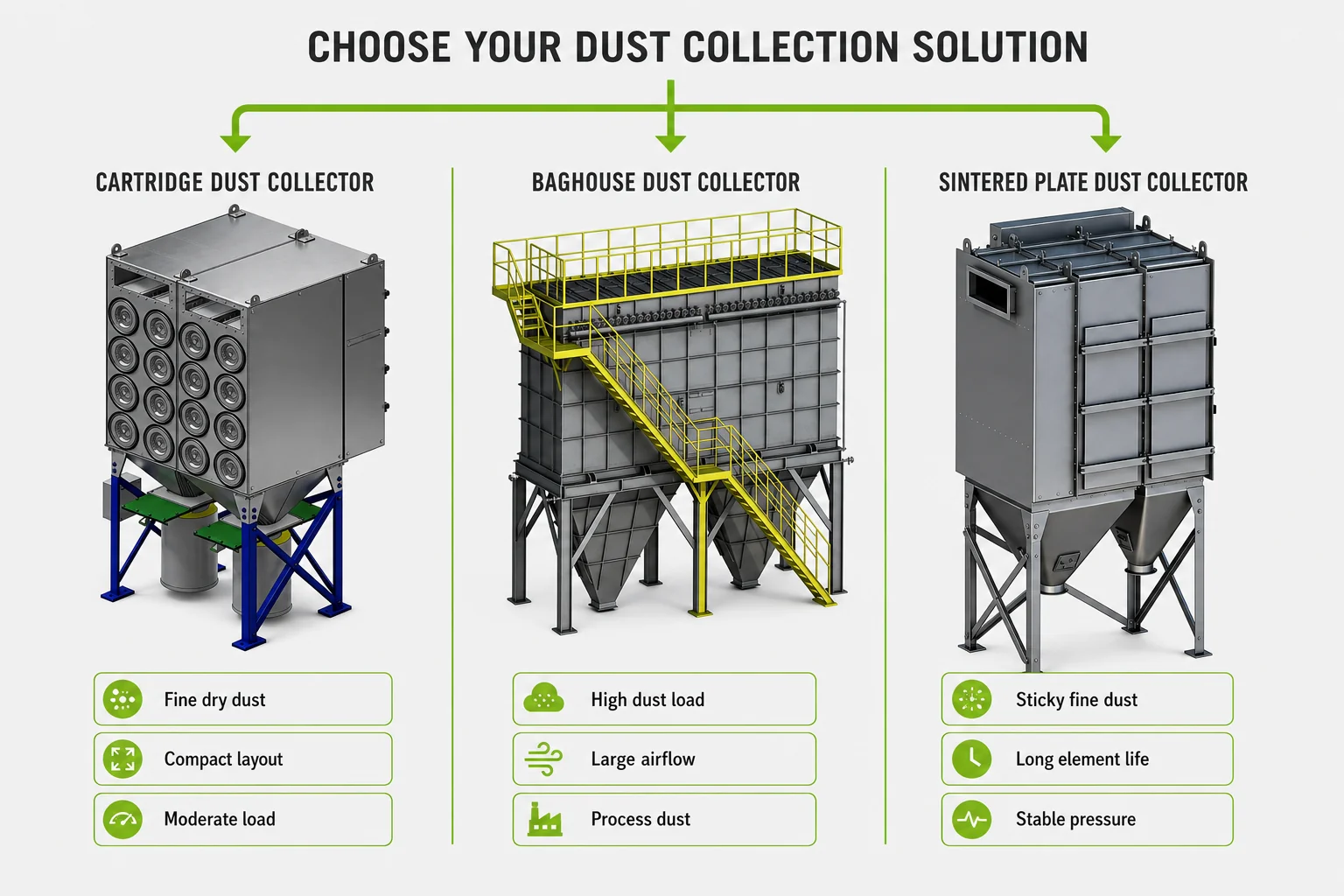
Collector type should be selected after dust loading, particle size, temperature, moisture and maintenance needs are reviewed.
If the project uses bag filters, the filter media should also be reviewed. See AIER’s article on dust collector filter bags for material selection factors such as temperature, moisture, chemical exposure and PTFE membrane needs.
Common Dust Collection System Design Mistakes
Many dust collection problems come from early design assumptions rather than collector quality. The most common mistakes include:
- Sizing from the collector outward: choosing a collector model before capture points and duct losses are known.
- Ignoring simultaneous operation: adding every pickup point or underestimating peak production airflow.
- Using long duct routes with too many elbows: increasing static pressure and reducing real airflow at the hood.
- Missing dust properties: treating hot, wet, sticky, abrasive and combustible dust as the same design problem.
- Leaving no maintenance space: making filter replacement, hopper cleaning or fan access difficult.
- Skipping safety review: assuming a dust collector alone solves combustible dust, spark or explosion concerns.

Low capture airflow, excessive duct resistance, poor access and the wrong collector type can turn a clean design into a difficult operating system.
A good design review should also consider future capacity. If a plant expects to add more production lines or new dust sources, the system should be planned with realistic expansion points instead of forcing a later retrofit.
Information AIER Needs Before Sizing a System
Before AIER can recommend a dust collection system configuration, prepare the following project data:
- Dust source list, process description and working schedule.
- Plant layout, equipment positions and available collector location.
- Required capture points, hood dimensions or enclosure openings.
- Dust type, particle size, bulk density and dust loading if available.
- Air temperature, moisture, oil mist, acid gas or chemical exposure.
- Whether the dust is combustible, explosive, toxic or regulated.
- Expected airflow or current fan / duct data if replacing an old system.
- Discharge method: bin, drum, screw conveyor, rotary valve or other route.
- Maintenance space, installation restrictions and future expansion plans.
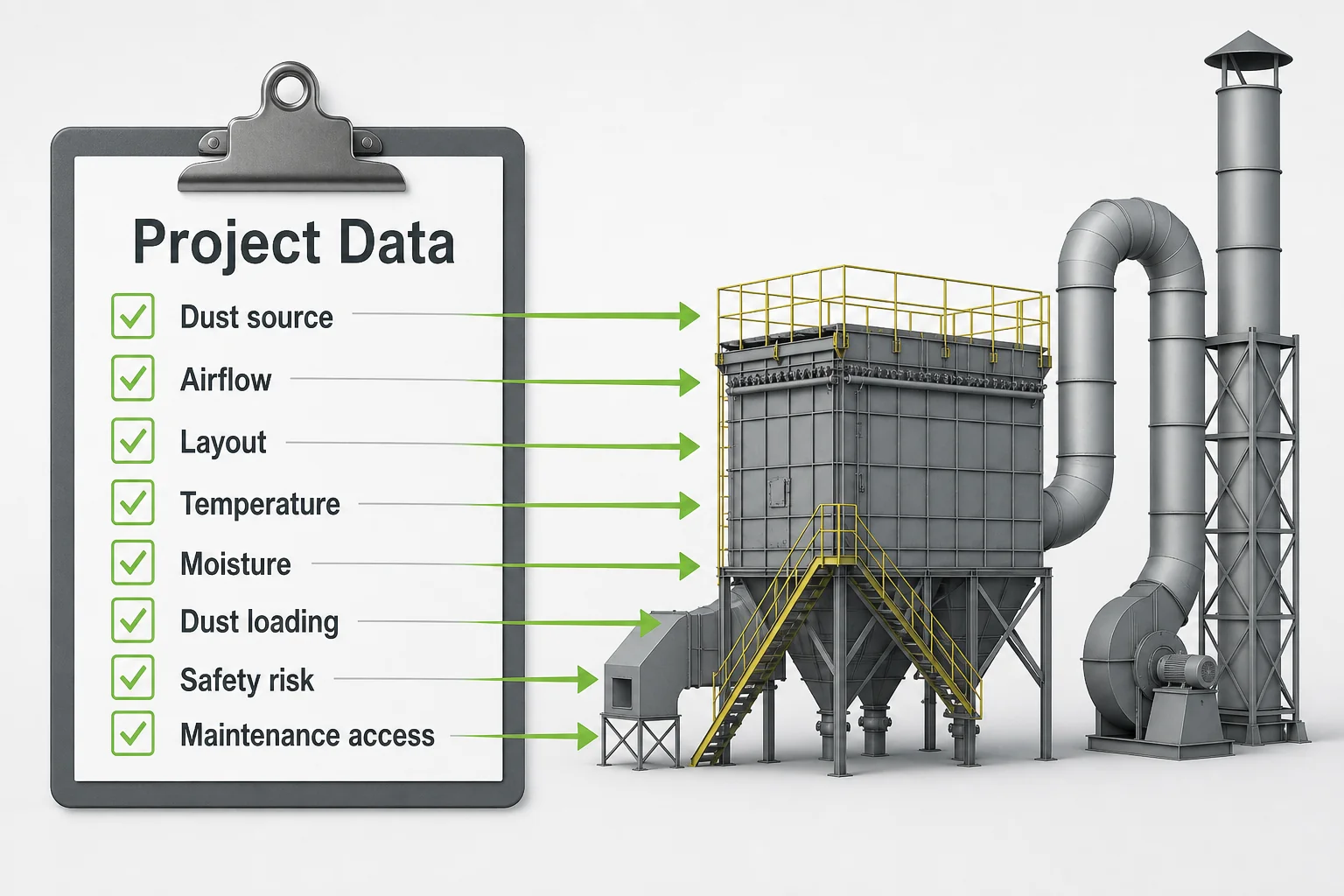
Project data helps the engineering team review airflow, duct routing, collector type, fan selection and maintenance access before equipment is quoted.
AIER Environmental Protection can review process conditions and recommend industrial dust collection systems for dry dust, fumes and powder handling. If you are planning a new line or correcting an underperforming system, contact AIER with your dust source list, layout and operating conditions.
FAQ
How do you design a dust collection system?
Start by mapping dust sources, capture points and operating schedules. Then estimate airflow, plan duct routing, calculate system resistance, review dust properties and select the collector type. The system should be checked as one airflow path, not as separate hoods, ducts and equipment pieces.
How do you size a dust collector for an industrial plant?
Dust collector sizing reviews airflow, dust loading, particle size, temperature, moisture, chemical exposure, filter area, air-to-cloth ratio and fan static pressure. The collector model should be selected after the capture points and ductwork are understood.
What information is needed before dust collector sizing?
Prepare the dust source list, layout, capture point dimensions, airflow targets, dust type, dust loading, temperature, moisture, chemical exposure, combustible dust status, discharge method and available maintenance space. Photos and existing equipment drawings are also useful.
Why does ductwork design affect dust collector performance?
Ductwork controls conveying velocity and pressure loss. Long duct runs, sharp elbows, leaks and poor branch balance can reduce airflow at the capture point, even if the collector itself is large enough. Fan selection should consider the full system resistance.
How do you choose between a cartridge collector and a baghouse?
A cartridge collector is often suitable for fine dry dust, fumes and compact layouts. A baghouse is usually better for higher dust loading, larger air volumes or process dust that needs filter bags. The final choice depends on dust properties, airflow, temperature, moisture and maintenance expectations.
Can a dust collector calculator replace an engineering review?
No. A dust collector calculator can support early airflow or duct estimates, but it cannot evaluate plant layout, dust hazards, process changes, maintenance access or safety requirements. Industrial projects should still be reviewed with real operating data.